Shop Solver
Compound Angle Calculator
Command path: Tools->Compound Angle
This tool calculates the rotation and
tilt angles required to mill a flat facet or drill a hole on
a compound angle.
The
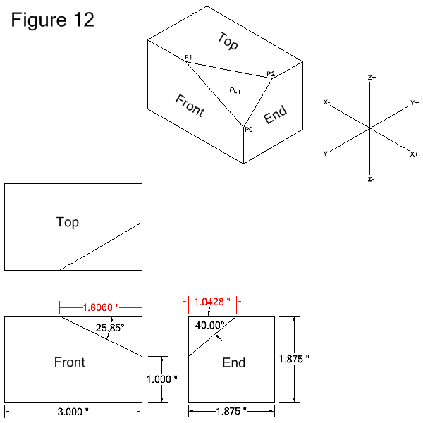
following 3 examples for milling a compound facet refer to Figure 12
below. All given dimensions are shown in black. Calculated
dimensions are shown in red. The examples assume that the facet
will be milled with the bottom of the cutter. Click here for an example for
drilling a hole on a compound angle.
Note: The Triangle Solver tool can be used to determine the calculated dimensions shown in Figure 12.
Example for milling a compound facet via a plane definition
Example for milling a compound facet via the definitions of 3 points
Example for milling a compound facet via the definitions of 2 vectors
Example 1: Milling a Facet via a Plane Definition
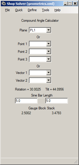
In the tool image above the plane PL1 has been selected in the Plane drop-down list. Click here
for the plane definition descriptions. In this example the plane
was defined as going through 3 nonlinear points. Figure 12 above shows
the 3 points named P0, P1 and P2. For reference the coordinates
of the 3 points are:
P0 = X0 Y0 Z0
P1 = X-1.806 Y0 Z0.875
P2 = X0 Y1.0428 Z0.875
Selecting
the plane automatically calculates the rotation and tilt angles
required to mill the facet. The angles are in degrees and are
shown below the Vector drop-down fields (see Note 1).
Gauge
block stacks for the rotation and tilt angles may be determined by
entering the lengths of the sine bars to be used. In the tool
image sine bar lengths of 5.0 were specified.
Example 2: Milling a Facet via 3 Point Defintions
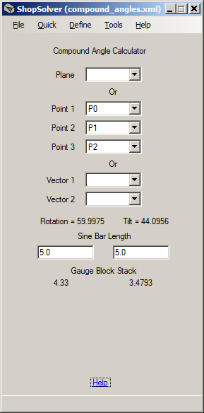
In
the tool image above 3 points have been selected, each representing a
corner of the facet to be milled. Click here
for the point definition descriptions. Figure 12 above shows
the 3 points named P0, P1 and P2. For reference the coordinates
of the 3 points are:
P0 = X0 Y0 Z0
P1 = X-1.806 Y0 Z0.875
P2 = X0 Y1.0428 Z0.875
When all 3 points have been selected the tool automatically calculates the rotation and tilt angles
required to mill the facet. The angles are in degrees and are
shown below the Vector drop-down fields (see Note 1).
Gauge
block stacks for the rotation and tilt angles may be determined by
entering the lengths of the sine bars to be used. In the tool
image sine bar lengths of 5.0 were specified.
Example 3: Milling a Facet via 2 Vector Defintions
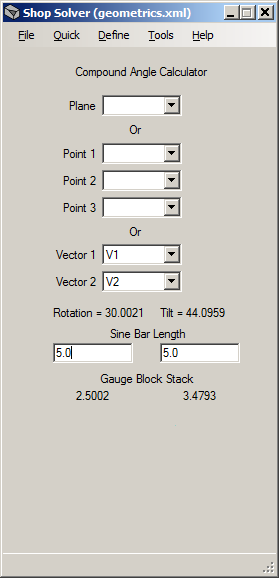
In the tool image above, 2 vectors have been selected. Click here
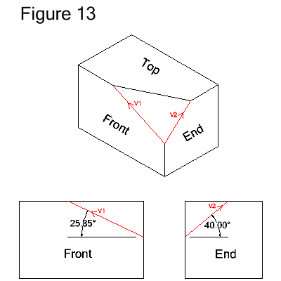
for the vector definition descriptions. Each
vector represents an edge on the facet. Figure 13 below shows the 2
vectors, named V1 and V2, in red. The vectors are defined as
"Length (Magnitude) and an Angle in a Plane". For reference the
vector definitions are:
V1=VECTOR/LENGTH,1.0,ATANGL,25.85,ZXPLAN
V2=VECTOR/LENGTH,1.0,ATANGL,40.0,YZPLAN
The vector properties are:
- The length of both vectors is 1.0. The lengths are not important -- they just need to be greater than zero.
- V1 is defined in the ZX plane at an angle of 25.85 degrees.
- V2 is defined in the YZ plane at an angle of 40.0 degrees.
Note: Any 2 edges
of the facet may be used. For example:
V3=VECTOR/LENGTH,1.0,ATANGL,-154.15,ZXPLAN $$ complement of angle of V1 (front view)
V4=VECTOR/LENGTH,1.0,ATANGL,30.0,XYPLAN $$ angle when looking down at top view
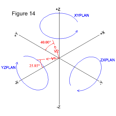
Figure
14 below depicts another representation of vectors V1 and V2. The blue circles
show the direction of positive angles around their respective axes.
Positive angles are counter-clockwise and determined by looking
along an axis from the positive end toward the origin. Zero
degrees is at 3 o'clock when looking along an axis.
When both vectors have been selected the tool automatically calculates the rotation and tilt angles
required to mill the facet. The angles are in degrees and are
shown below the Vector drop-down fields (see Note 1).
Gauge
block stacks for the rotation and tilt angles may be determined by
entering the lengths of the sine bars to be used. In the tool
image sine bar lengths of 5.0 were specified.
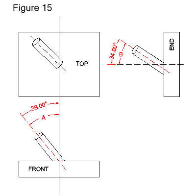
Example 4: Drilling a Hole via 2 Vector Definitions
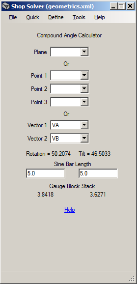
In
the tool image above, 2 vectors have been selected. The vectors
represent the angles of a cylinder's centerline, as shown in Figure 15 below.
(Click here
for the vector definition descriptions.) The
vectors, named VA and VB, are associated with angles "A" and "B".
The vectors' angles are those required to rotate the cylinder
into a vertical position. Note: The angles are not the
compound angles required to drill the hole, just the values given on the print or in
the specification.
In Figure 15 below, VA must be rotated 39.0 degrees
in the ZX plane to become vertical. VB must be rotated 34.0
degrees in the YZ plane to become vertical. Refer to Figure 14 above for how to determine direction of rotation. Both vectors are defined as
"Length (Magnitude) and an Angle in a Plane". For reference the
vector definitions are:
VA=VECTOR/LENGTH,1.0,ATANGL,39.0,ZXPLAN
VB=VECTOR/LENGTH,1.0,ATANGL,34.0,YZPLAN
The vector properties are:
- The length of both vectors is 1.0. The lengths are not important -- they just need to be greater than zero.
- VA is defined in the ZX plane at an angle of 39.0 degrees.
- VB is defined in the YZ plane at an angle of 34.0 degrees.
When both vectors have been selected the tool automatically calculates the rotation and tilt angles
required to drill the hole. The angles are in degrees and are
shown below the Vector drop-down fields (see Note 1).
Gauge
block stacks for the rotation and tilt angles may be determined by
entering the lengths of the sine bars to be used. In the tool
image sine bar lengths of 5.0 were specified.
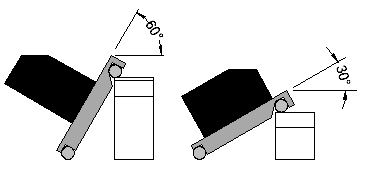
Note 1
Depending upon the set-up, it may be
necessary to calculate and use the complement of an angle, especially if the required sine bar angle is greater than 45 degrees.
This is because the gauge block stack required to obtain the
angle may be too great for setting the sine bar. Therefore the
angle of the sine bar and the part surface contacting the sine bar must
be altered. An example is shown below. On the left the part
to be milled is resting on its narrow width causing the angle of the
sine bar to be too steep. On the right the part is resting on its
length and the angle of the sine bar is acceptable. Again,
depending upon the set-up, this may need to be applied to either the
tilt or rotation angle.