Shop Solver
Line/Line Tool
Command path: Quick->Line/Line
The purpose of this tool is to determine the intersection point of 2 lines, if any.
Quick Start
This tool is two-dimensional (2D). Both
lines must lie in the same plane and the plane must be parallel with
the XY plane. Refer
to the Line definitions for
information about three-dimensional lines and operations on them.
To find the intersection point of two lines:
1)
In the box labeled "Line 1", select whether the line will be
defined as passing through a known point at an angle (Point/Angle) or
passing through two known points (Point/Point).
2)
For "Point/Angle" enter the X and Y values of the point and the
angle in degrees. For "Point/Point" enter the X and Y values for
both points.
3) Repeat steps 1 and 2 for Line 2.
4) Click the Calculate button. If the button is disabled then tab to or click on another field (such as the Offset field). The point of intersection is shown in the fields above the button.
For information about the Offset fields click here.
Overview
The
application window is divided into three sections. The upper two
sections are for defining the two lines. The lower section
displays the result of the intersection calculation. The buttons
in the lower section are described below.
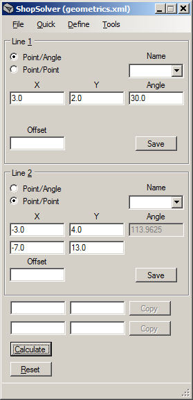
Image LineLine1

Referring to image LineLine1 above, a line may be defined as:
1) passing through a point and at an angle (in degrees) with the positive X-axis, or
2) passing through two points.
The radio buttons "Point/Angle" and "Point/Point" are used to specify which type of line definition is desired. Figure
1 below shows line L1 passing through X3.0, Y2.0 and at an angle
of +30 degrees with the positive X-axis. Line L2 passes through
the two points X-3.0, Y4.0 and X-7.0, Y13.0. Both lines are shown
entered into the line definition sections in image LineLine1 above.

Figure
2 shows how positive and negative angles are determined.

Figure 3 shows another example of two lines, L1 and L2, that intersect:

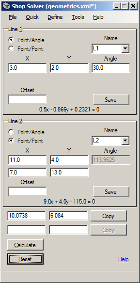
Image LineLine2

Image
LineLine2 shows the coordinates of the points and angles of lines
L1 and L2 from Figure 3. The angle shown for Line 2 was
calculated by Shop Solver after the coordinates of the two points were
entered. The angle field is disabled and shown with a gray
background because it is only for reference in a Point/Point definition.
The
bottom section of Image LineLine2 shows the point of intersection of
lines L1 and L2 after the Calculate button was clicked. The Copy button, when clicked, copies the X and Y values of the point of
intersection to the clipboard. The Reset button clears all
fields in the window.
The Name fields are used in conjunction with the Save buttons.
When a name is specified the Save
button stores the line
definition in memory. The definition may be recalled later by
selecting the name from the Name field's drop down list. Saving a
definition in memory is optional and is not required for calculating
intersections. If not saved to a file, all definitions saved in memory are lost when Shop Solver is closed. See the File command for saving and loading
definitions to and from a file.
A
Point definition may be created by right-clicking with the mouse on any
of the X fields. A pop-up menu will appear with a Create Point
command. The command will take you to the point definition
tool and the X, Y, and Z (Z when applicable) values will be
automatically entered into the proper fields. For more about
point definitions click here.
If
any points have been saved in memory then their X and Y values may
be automatically pasted into the line definition fields.
Right-click on any X field in the line definitions and a pop-up
menu will appear with the names of all points currently saved in
memory. Select a point to paste its X and Y values into the
fields.
All
numeric entry fields in Shop Solver can evaluate and solve mathematical
expressions. You may enter expressions using the common
arithmetic operators +, -, *, /, (, ), %, and ^. In addition 30+
functions are supported such as trigonometric functions, common math
functions (square and cube roots, absolute values, min/max, etc.) and
common shop functions such as surface feet per minute (SFM) to RPM, inch to
millimeter, and others. Expressions are evaluated when an entry field
loses the focus by tabbing to or clicking on something else. For
a full description of this feature click here.
Line Offsets
The
usage of the Offset fields is depicted in Figure 4. The outline of
a simple part is shown in black and the path of a 0.5" end mill around
the part is shown in green. The points of intersection of the end
mill's centerline path are determined by:
1) Defining the lines in black as described above, and
2)
Specifying an offset of 1/2 of the end mill's diameter in the Offset
fields. In this example the offset values are +/- 0.25.
The
signs of the offsets (+/-) determine their direction.
In general, a positive offset is used when the relative direction
of the required line shift is up. A negative offset is used when
the relative direction of the required line shift is down.
Vertical lines are an exception as an offset up or down has no
meaning. Therefore a positive offset shifts a vertical line to
the right and a negative offset shifts it to the left.

Referring to Figure 4 the line offsets are as follows:
L1: -0.25
L2: +0.25
L3: +0.25
L4: +0.25
L5: +0.25
L6: -0.25
Figure 5 depicts offset directions in greater detail.


