MACHIN/ACORNL
PARTNO CYCLE/TURN 1
SEQNO/1000,INCR,10,1
PRINT/ON $$ This controls the printing of canon data after each geometric definition
CLPRNT $$ This controls the printing of postprocessor data. Options are "ON", "OFF", AND "OPTION".
SYN/ AA,ATANGL, CA,CANON, CE,CENTER, CI,CIRCLE, CY,CYLNDR, DC,DNTCUT, $
FR,FEDRAT, GB,GOBACK, GD,GODLTA, GF,GOFWD, GL,GOLFT, GR,GORGT, $
GT,GOTO, IP,INDIRP, IV,INDIRV, IT,INTOF, LF,LEFT, LI,LINE, $
MX,MATRIX, OB,OBTAIN, PA,PARLEL, PD,PENDWN, PU,PENUP, PP,PERPTO, $
PL,PLANE, PT,POINT, RA,RADIUS, RT,RIGHT, TT,TANTO, TH,THICK, $
TA,TLAXIS, TL,TLLFT, TN,TLON, TR,TLRGT, VE,VECTOR, XL,XLARGE, $
XS,XSMALL, YL,YLARGE, YS,YSMALL, ZL,ZLARGE, ZS,ZSMALL, RP,RAPID
HOME=PT/5,5,5
LX=LI/XAXIS
LY=LI/YAXIS
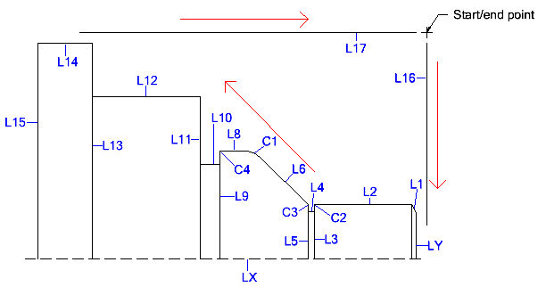
L1=LI/(PT/0,(.86/2)),AA,30,YAXIS
L2=LI/PA,LX,YL,(1.0/2)
L3=LI/PA,LY,XS,(1.0-.062)
L4=LI/PA,LX,YL,(.88/2)
L5=LI/PA,LY,XS,1.0
L6=LI/(PT/-1.0,(1.0/2)),AA,-45,XAXIS
L8=LI/PA,LX,YL,(2.0/2)
L9=LI/PA,LY,XS,(2.0-.188)
L10=LI/PA,LX,YL,(1.75/2)
L11=LI/PA,LY,XS,2.0
L12=LI/PA,LX,YL,(3.0/2)
L13=LI/PA,LY,XS,3.0
L14=LI/PA,LX,YL,(4.0/2)
L15=LI/PA,LY,XS,3.5
L16=LI/PA,LY,XL,.1
L17=LI/PA,L14,YL,.1
C1=CI/YS,L6,YS,L8,RA,.25
C2=CI/YS,L2,XL,L3,RA,.010
C3=CI/YS,L6,XS,L5,RA,.010
C4=CI/YS,L8,XL,L9,RA,.010
PL0=PL/0,0,1,0
$$************* ROUGH TURN, .032 RADIUS TOOL **************************
PPRINT
PPRINT ROUGH TURN, .032 RADIUS TOOL
$$ This macro defines the bulk of the profile path
$$ along with the additional statements enclosed by the
$$ INDEX statements. This macro is also called when
$$ the finish passes are defined. Using a macro is not
$$ required. It just simplifies part programming and
$$ saves a bit of typing.
RTURN=MACRO
GL/L2
GR/L6
GF/C1
GF/L8
GR/L11
GF/(CI/XS,L11,YS,L12,RA,.010)
GF/L12
GR/L13
GF/(CI/XS,L13,YS,L14,RA,.010)
GF/L14,PAST,L15
GO/PAST,L17
RP,GO/PAST,L16
TERMAC
RESET
TURRET/1,1
ORIGIN/54
SPINDL/500,SFM,CLW,MAXRPM,10000
COOLNT/ON
FROM/HOME
CUTTER/.084 $$ declare oversized cutter diameter for rough turning
FEDRAT/.008 $$ declare a default feedrate just to be safe
$$ In the following CYCLE/TURN command:
$$ 1 = The index number that defines the closed profile path
$$ .064 = The actual cutter diameter. Note that an oversized cutter is declared above which will leave .010 on all surfaces for clean up.
$$ .060 = The radial depth of cut.
$$ .008 = The axial feedrate.
$$ .003 = The radial (i.e. plunge) feedrate.
$$ Note that the tool path for the CYCLE/TURN is not (and must not) be transformed in any manner.
$$ The finish operation coded later uses TRACUT per standard lathe programming.
CYCLE/TURN,1,.064,.060,.008,.003
INDEX/1
RP,GO/L16,PL0,L17 $$ this is the start/end point and matches the ending location in the macro
RP,GO/L16,PL0,L1
TR,GR/L1
CALL/RTURN
INDEX/1,NOMORE
COOLNT/OFF
SPINDL/OFF
RP,GOHOME
OPSTOP
$$************* FINISH FACE AND TURN, .032 RADIUS TOOL ****************
PPRINT
PPRINT FINISH FACE AND TURN, .032 RADIUS TOOL
RESET
TURRET/2,2
ORIGIN/54
SPINDL/500,SFM,CLW,MAXRPM,10000
COOLNT/ON
FROM/HOME
CUTTER/.064
FEDRAT/.008
TRACUT/(M1=MATRIX/TRANSL,-.032,-.032,0) $$ TRACUT by the actual tool nose radius.
$$ FINISH FACE
CUTCOM/LEFT
RP,GO/(LI/PA,LY,XL,.05),PL0,(LI/PA,L2,YL,.05)
GO/LY
GO/PAST,LX
CUTCOM/OFF
GO/PAST,(LI/PA,LY,XL,.05)
$$ FINISH TURNING
CUTCOM/RIGHT
RP,GO/(LI/PA,LY,XL,.05),PL0,PAST,L1
TR,GL/L1
CALL/RTURN
CUTCOM/OFF
TRACUT/NOMORE
COOLNT/OFF
SPINDL/OFF
RP,GOHOME
OPSTOP
$$ *************** 1/16 (.062) GROOVING, .010 RADIUS ******************
PPRINT
PPRINT 1/16 (.062) GROOVING, .010 RADIUS
RESET
TURRET/3,3
ORIGIN/55
SPINDL/500,SFM,CLW,MAXRPM,3000
COOLNT/ON
FROM/HOME
CUTTER/.020
TRACUT/(M2=MATRIX/TRANSL,-.010,-.010,0)
RP,GO/L5,ON,PL0,(LI/PA,L2,YL,.050)
FEDRAT/.002
GO/L4
RP,GO/PAST,(LI/PA,L2,YL,.050)
GO/L6
TL,GL/L6
GF/C3,TT,L5
RP,GO/PAST,(LI/PA,L2,YL,.050)
TRACUT/NOMORE
TRACUT/(M3=MATRIX/TRANSL,-.052,-.01,0) $$ X VALUE = -(TOOL WIDTH - TOOL RADIUS)
RP,GO/ON,(LI/(PT/CE,C2),PP,LX)
GO/C2
TR,GR/C2,TT,L3
RP,GO/PAST,(LI/PA,L2,YL,.050)
TRACUT/NOMORE
COOLNT/OFF
SPINDL/OFF
RP,GOHOME
OPSTOP
$$ *************** 1/8 (.125) GROOVING, .010 RADIUS *******************
PPRINT
PPRINT 1/8 (.125) GROOVING, .010 RADIUS
RESET
TURRET/4,4
ORIGIN/55
SPINDL/500,SFM,CLW,MAXRPM,3000
COOLNT/ON
FROM/HOME
CUTTER/.020
TRACUT/M2
RP,GO/L11,ON,PL0,(LI/PA,L12,YL,.050)
FEDRAT/.002
GO/L10
RP,GO/PAST,(LI/PA,L8,YL,.050)
TRACUT/(M4=MATRIX/TRANSL,-.115,-.01,0) $$ X VALUE = -(TOOL WIDTH - TOOL RADIUS)
RP,GO/L9
GO/L10
TRACUT/NOMORE
TRACUT/M2
GO/L11
RP,GO/PAST,(LI/PA,L8,YL,.050)
TRACUT/NOMORE
TRACUT/M4
RP,GO/ON,(LI/(PT/CE,C4),PP,LX)
GO/C4
TR,GR/C4,TT,L9
RP,GO/PAST,(LI/PA,L8,YL,.050)
TRACUT/NOMORE
COOLNT/OFF
SPINDL/OFF
RP,GOHOME
OPSTOP
$$********** 90 DEGREE SPOT DRILL TO .460 DIAMETER ********************
PPRINT
PPRINT 90 DEGREE SPOT DRILL TO .460 DIAMETER
RESET
TURRET/5,5
REVS=(500*3.82)/.5 $$ RPM = (SFM * 3.82) / dia
SPINDL/REVS,RPM,CLW
COOLNT/ON
FROM/HOME
RP,GOTO/1,0,0
CYCLE/DRILL,(-.460/2),.1,.002
CYCLE/OFF
COOLNT/OFF
SPINDL/OFF
RP,GOHOME
OPSTOP
$$******************* 7/16 (.438) DRILL THRU **************************
PPRINT
PPRINT 7/16 (.438) DRILL THRU
RESET
TURRET/6,6
REVS=(500*3.82)/.438 $$ RPM = (SFM * 3.82) / dia
SPINDL/REVS,RPM,CLW
COOLNT/ON
FROM/HOME
RP,GOTO/1,0,0
DPTH=3.5+(TANF(31)*(.438/2))+.01
CYCLE/DEEP,-DPTH,.1,.004,(.438/2)
CYCLE/OFF
COOLNT/OFF
SPINDL/OFF
RP,GOHOME
OPSTOP
$$*********************** 1/4-18 NPT TAP ******************************
PPRINT
PPRINT 1/4-18 NPT TAP, DEPTH IS ONLY A GUESS
RESET
TURRET/7,7
SPINDL/300,RPM,CLW
COOLNT/ON
FROM/HOME
RP,GOTO/1,0,0
CYCLE/TAP,RIGHT,-.5,.1,(1/18) $$ Depth is only a guess.
CYCLE/OFF
COOLNT/OFF
SPINDL/OFF
RP,GOHOME
OPSTOP
$$ *************** 1"-12 EXTERNAL THREAD ******************************
PPRINT
PPRINT 1"-12 EXTERNAL THREAD
RESET
TURRET/8,8
SPINDL/300,RPM,CLW
COOLNT/ON
FROM/HOME
RP,GOTO/.1,.55,0
$$ pitch, major diameter, z, depth of first cut, min depth of cut, depth of last pass, pull out, taper, infeed angle, spring passes
THREAD/(1/12),(1-2*(1/12)*.61343),(-1.0+.031),.01,.001,.001,0,0,60,3
COOLNT/OFF
SPINDL/OFF
RP,GOHOME
REWIND
FINI
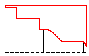
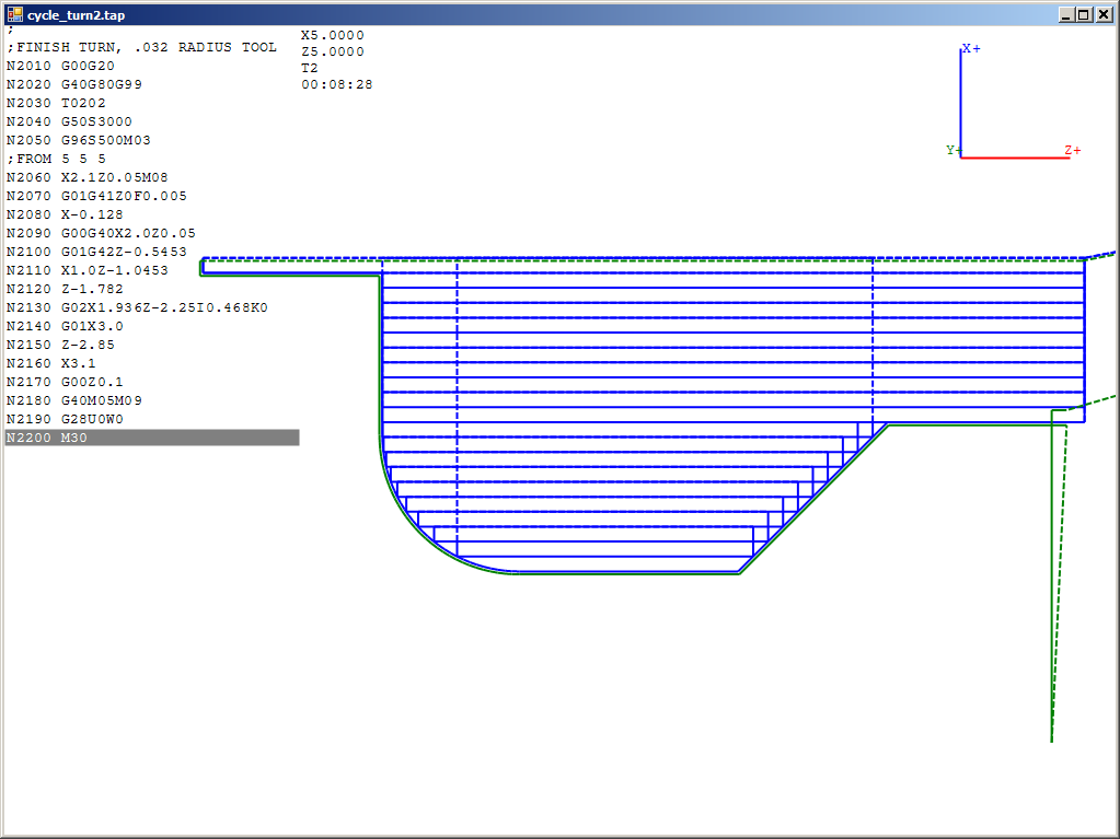
Here is another plot showing OD roughing and finishing with an undercut:
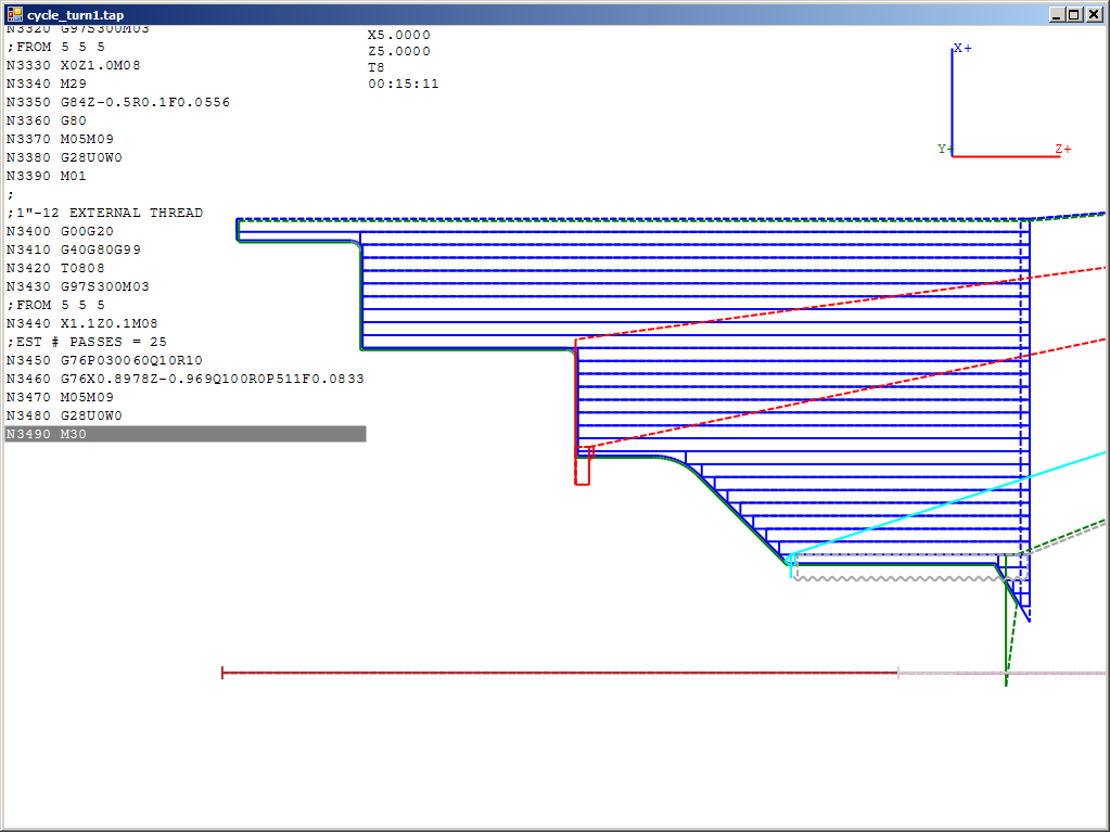
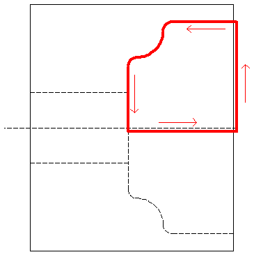
Here is an example path and plot showing roughing out a bore:
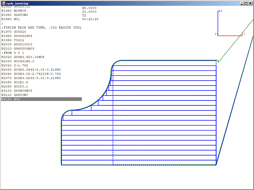
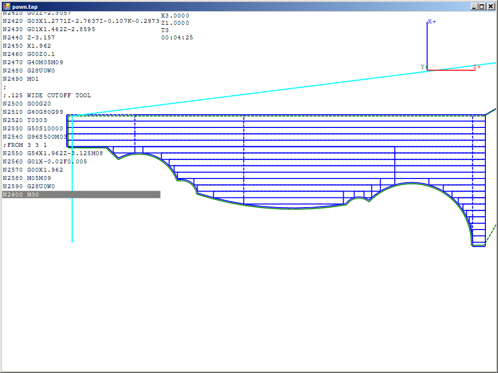
And here is a chess pawn being roughed and finished turned and parted off:
