Shop Solver
Countersinks/Counterbores
Command path: Tools->C'Sinks/C'Bores
This tool has 3 features:
1) It calculates the depth of cut for a countersink with a specified included angle to obtain a desired diameter.
2)
As an aid for measuring, it calculates the height of any size ball that is in contact with the
countersink, and the adjustment to the tool depth needed to bring the
countersink diameter to size.
3) A reference tool that provides clearance hole and counterbore diameters for inch and metric cap screws.
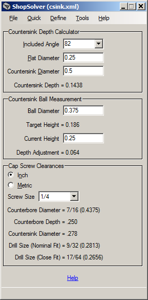
Tool Image

Countersink Depth Calculator
The
Countersink Depth Calculator determines the depth of cut required to
obtain a specified countersink diameter. It consists of 3 entry
fields and the calculated depth of cut. The 3 entry fields are:
- Included
Angle: A drop-down list of common included angles. You may
select an angle from the list or enter a custom angle in the entry
field.
- Flat Diameter: The diameter of the flat ground
onto the bottom of the countersink. A flat diameter of zero
assumes the countersink has a theoretical sharp point. See Figure
11 below.
- Countersink Diameter: The desired diameter of the countersink.

Figure
11 depicts an 82 degree countersink with a flat diameter of .250".
Using it as an example, to obtain a .500" diameter
countersink:
1) Select 82 from the Included Angle drop-down list or enter 82 into the entry field.
2) Enter .25 into the Flat Diameter entry field.
3) Enter .5 into the Countersink Diameter entry field.
4) Press Enter or tab to or click on any other field. The depth of cut (0.1438) is shown in the Depth label below the Countersink Diameter entry field.
The
calculator can also be used to determine the length of a drill point.
For example, to determine the drill point length of a .375"
diameter drill with a standard 118 degree grind:
1) Select 118 from the Included Angle drop-down list.
2) Enter 0 into the Flat Diameter entry field.
3) Enter .375 into the Countersink Diameter entry field.
4) Press Enter or tab to or click on any other field. The length of the drill point (0.1127) is shown in the Depth label.
Countersink Ball Measurement
The
Countersink Ball Measurement section calculates the height of any size
ball that is in contact with the countersink. It also calculates
the depth adjustment required to obtain the desired diameter.
Figure
11a below shows 3 examples of different diameter balls used to measure
an 82 degree countersink that is .75" in diameter. The balls are
shown in red along with the distances from the surface plane to the
tops of the balls. The image on the left depicts a ball that only
contacts the countersink along its rim where the flat surface plane
intersects the cone of the countersink. The image in the middle
depicts a ball that contacts the surface of the countersink's cone and
extends above the surface plane. The image on the right depicts a
ball that contacts the surface of the countersink's cone and lies below
the surface plane.

To determine the height of a specified ball diameter above or below the surface plane:
1) Use the Countersink Depth Calculator as described above to determine the depth of the countersink.
2) Enter the ball diameter in the Ball Diameter field.
3) Press Enter or tab to or click on any other field. The height of the top of the ball is shown in the Target Height label.
To
determine the distance required to increase or decrease the depth of
the countersink in order to obtain the desired diameter (assuming the
material has already been countersunk):
1) Calculate the target height of the ball as described above.
2) Measure the height of the top of the ball resting in or on the countersink and enter the distance in the Current Height field.
3) Press Enter
or tab to or click on any other field. The distance
required to increase or decrease the depth of cut is shown in the Depth Adjustment
label. Positive values mean that the countersink's depth of
cut must be increased; negative values mean that the countersink's
depth of cut must be decreased.
Cap Screw Clearances
As shown in the Tool Image above,
select either "Inch" or "Metric" and the screw size from the drop-down
list. The counterbore and clearance hole dimensions are shown in the
fields below the drop-down list.


