Jan 29, 2020
New:
CYCLE/TURN lathe post-processor command for OD and ID rough stock
removal. Similar to the G71 command provided by some CNC lathe
controllers, this automatically generates the rough turning passes
needed to remove excess stock during turning and boring operations.
See the post-processor documentation for the CYCLE command for a full description.
Jan 21, 2020
Recently added: LETTER post-processor command: Mill/engrave alphanumeric strings.
Jan 12, 2020
If anyone would like to try any of the following applications, contact me at aptfan@frenetec.com.
All I ask is that you let me know about any bugs/problems and
suggestions for improvement. The post-processor currently
supports mills and lathes for the Centroid, Fanuc, Haas and Tormach
controllers. Follow the links below to browse the
applications' documentation.
APT360 pre-processor
APT360 post-processor
Post-processor options file
NC plotter
APT source file template
APT command file
I
can also provide a copy of the APT360 compiler (apt360.exe for Windows) if
you need it. I built if from the free source code as described
earlier (see https://sourceforge.net/p/aptos/apt360/ci/master/tree) and fixed a bug pertaining to defining a point as a location in a PATERN.
The editor is not ready for public consumption.
Jan 11, 2020
TRACUT and COPY cutter location transformations are stored in the
"enhanced" binary cutter location file PRO.TAP (along with all other
cutter location records). If your APT program uses either TRACUT
or COPY you must post-process the file PRO.TAP rather than CL.TAP.
To determine which file to post-process just scan either
CL.TAP or PRO.TAP for TRACUT and COPY record types (see below for the
record type definition). If the scanned file contains either
record then PRO.TAP must be used. Technically TRACUT and COPY are post-processor commands so you
can use CL.TAP if you provide your own implementations.
Sep 24, 2019
I
have been sidetracked by other projects so it has been a while.
Something I have been meaning to do is document the record
structure of the APT360 binary cutter location file, CL.TAP.
Hopefully
this information will be of help to anyone wishing to write their own
post-processor. Note: This information is for the Windows
platform and is the best of my knowledge up to this date. It is
not exhaustive as I certainly have not tested every feature of the APT
language. Please contact me if anything is incorrect, has
been omitted, or if something could use further explanation.
Each record begins with a block that identifies and
describes the record. Following the block is the data associated
with the record. This pattern repeats for the rest of the records
in the file. The structure of the block is as follows:
RECNO (4-byte integer): This record's record number.
COUNT (4-byte integer): Count of 8 byte entries in this record's data (8 * count = the length of the data in bytes).
RECTYPE (4-byte integer): The record type.
SUBTYPE (4-byte integer): The record subtype.
DATA (8 * count bytes): The record's data.
The record types (RECTYPE) that I have discovered are:
1000:
The record number (RECNO in the CLPRNT file) and the Input Sequence
Number (ISN). The ISN is in the SUBTYPE field. All other
record types are preceded by a 1000 record. Hint: Every APT
program line can be identified by its ISN number in the CLPRNT file.
2000:
Post-processor commands. The specific command is in the
SUBTYPE field. The record's DATA is formatted to match the
commands' parameters which, in turn, are specific to the
post-processor implementation. As such, I cannot document each
command here. Suffice it to say that the data can contain bytes
that are characters, integers mapped to APT minor words, and Doubles.
3000:
I believe this describes any nested surface definitions such as
LINE, CIRCLE, etc. SUBTYPE is either not used or I have not
determined how it is used. The specific surface type is
identified by a 4-byte integer beginning at byte 8 in the DATA.
The surface's name is in bytes 24-31. The subscript used
with the surface's name is a double-precision floating point number
(i.e. a Double) at byte 32. The remainder of the data are Doubles
and are the canonical values of the specific surface type.
4000: Unknown
5000:
For lack of a better description this is an actual cutter
location record. SUBTYPE identifies the source of the cutter
location. So far I have discovered SUBTYPEs: FROM
(3), GODLTA (4), GOTO (5) and SRFCNTD (6). The DATA may
contain a surface name, subscript, point coordinates and tool axis
vectors.
6000:
I believe this describes DNTCUT/CUT (SUBTYPE=1) and OUTTOL/INTOL
commands (SUBTYPEs 4 and 5), and cutter shape definition data (6).
7000: Unknown
8000: Unknown
9000: So far this looks like a MULTAX record when SUBTYPE=2. ON or OFF is a 4-byte integer at byte 0 in the DATA.
13000:
So far I have discovered 2 uses: SUBTYPE=3 is a
warning/error, although I don't follow the when's and why's of their
usage. SUBTYPE=4 is a CLPRNT and the 4-byte integer at byte 0 of
the DATA identifies the option value, if any.
14000: The FINI record.
As for the APT vocabulary, post-processor words and their values can be found here. Minor words and their values can be found here.
Jan 31, 2018
I
got sidetracked on the above when I began reviewing my implementation
of some of the post-processor words I have implemented. For
example I went too far with the CLEARP implementation and decided to
align it with Irvin Kral's definition. In short he defined it as
specifying a plane parallel only with the XY plane, relegating it
effective only to the Z-axis. As a result my post-processor now
supports RETRCT for a mill only.
I also reviewed my planned
implementation of the CLRSRF command. The documentation does not
specify what it should do and Irvin Kral does not cover it in his book
so I'm wondering if anyone has any input on the subject. Should
it just rapid to the specified surface using the shortest distance from
the current cutter location? Does anyone think it is a "must
have" option?
Jan 26, 2018
For
the past few days I have been attempting to learn how to get web
crawlers to index this page and re-index it regularly. It seems
to me that those in control of such matters are constantly changing the rules.
Today
I started the design of (for lack of better terminology) the
"Post-processor Vocabulary Word Assistant." Similar to the
Geometric Definition Assistant it will provide syntax help for
post-processor words with parameters. For example, when "COOLNT/"
is typed a window will pop up and display the syntax of the coolant
command and the parameters that the post-processor supports, such as
"ON" and "OFF". As another example typing "CYCLE/" will display
the syntax of the various cycle commands (such as drill, tap, etc.) and
their parameters.
Jan 19, 2018
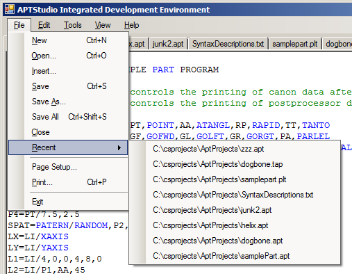
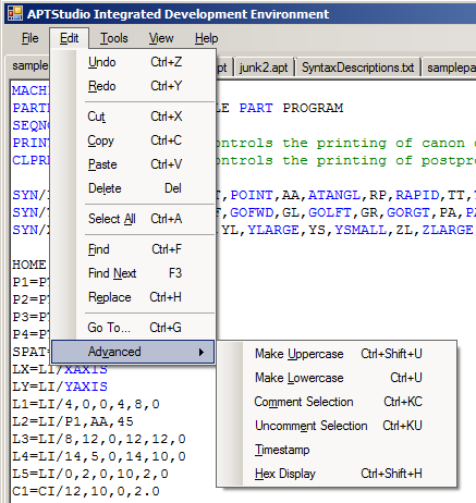
More screen shots of some of the editor features:


This
last image shows the Geometric Definition Assistant. It pops up
whenever a geometric definition is typed and is followed by a forward
slash. In this image "circle/" was typed and the user can select
one of the eleven possible circle definitions. Click the up and
down arrows or use the up and down arrow keys on the keyboard to
iterate through the possible definitions. Pressing the TAB
key inserts text which is a commented template for that definition.
Jan 17, 2018
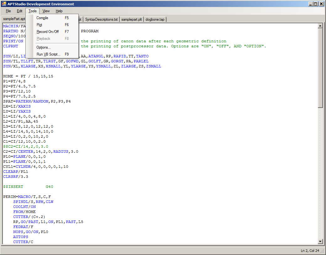
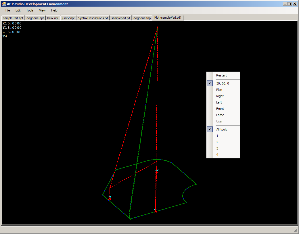
APT
Studio is an integrated development environment for creating,
compiling, post-processing and plotting APT programs. Some of the
features are:
- Editor:
multi-tabbed, syntax highlighting, geometric definition
assistant, run VB scripts, record and playback keystrokes, compile and
plot
- Post-processor:
4-axis mill, 2-axis lathe, virtual machine definitions (not user
accessible), user specified options (text file), tape and plot file
generation
- Plotter:
3D multi-color line plotter (3-axis), plot stop/opstop to stop/opstop,
single step forward and reverse, zoom in/out, rotate about 3 axes, XYZ
cutter location and tool number, multiple predefined view angles, plot
a single tool or all tools, plot post-processor generated plot file or
existing tape files
Here's a couple of screen shots of the integrated editor and plotter:


Jan 16, 2018
Welcome to
my APT home page! Here I, and hopefully other APT fans, will
discuss all things APT. I will also talk about some of the APT related
projects I have been working on the past few months. I'm just
getting started so relax and check back occasionally. Please feel
free to contact me at aptfan@frenetec.com.
But
first, what is APT? APT is an acronym for Automatically
Programmed Tool, or some variant thereof. It is a computer
language for programming Numerically Controlled (NC) machine tools and
other devices. If I remember my history correctly, the project
began in the 1950's as a joint effort between MIT and the Air Force to
help solve the complexities of programming the newly burgeoning
industry of computer controlled machine tools, otherwise known as NC
machine tools.
I have been amazed by what APT can accomplish
ever since my introduction to NC back in the mid 1970's. My first
career was as a machinist for Texas Instruments. I worked in the
Short Order and Non-metallic shops where I was assigned to change part
stock and push the buttons on an old 2 1/2 axis Cincinnati milling
machine. If you happen to remember machines that old you will
recall that the Z-axis was controlled via cams and set screws.
Also, the floor mounted controller read a punched tape that fed through the
tape reader and rolled up on wheels behind a clear polycarbonate door
on the front of the controller. Eventually I was one of the group
programming the shop's newer CNC tools. I have always been
grateful that TI gave me the opportunity to expand my skill set as both
a machinist and APT programmer. That's where I fell in love with
programming in general and have been doing so ever since.
So why
this web page dedicated to APT? I feel that it is worth paying
homage to such a great technological leap forward at a time when
manufacturing industrial might and computers were being integrated, all
right here in the great country of the USA. I also fear that APT
programming and programmers are being forgotten and that such valuable
skills and resources will be lost with the passage of time. CAM
is the reigning king today as the industry has taken mighty
technological leaps forward. APT may be a dinosaur but it is
still around, doing all sorts of amazing calculations
and helping to machine amazing parts on even more amazing tools.
I
wish to express my thanks to the group of individuals that ported the
IBM 360 version of APT to Unix and Windows. I obtained the freely
distributable source code (a project entitled "Aptos", which is available for download at https://sourceforge.net/p/aptos/apt360/ci/master/tree)
and compiled it with Microsoft's Visual Studio Express 2015. As I
recall I had to tweak a couple of headers and fixed a bug related to
defining a point as a member of a pattern, but so far I've had good
luck with the port. I have not pushed the code to its limits by
any means, as I've been busy with developing projects related to making
it easier to use, but so far it seems to work very well. There
are a couple of known issues with it, which are are documented in the
README file included with the source code, but I have not found them to
be an impediment. So
thanks Aptos folks for your hard work and dedication to APT!
Up
to this point I have written a post-processor targeting Fanuc
controllers for
mills and lathes, a synonym parser (because the APT port does not
support synonyms), an editor and a 3D line plotter. My target
environment is Microsoft Windows and all coding is done in C#.
Update: The post-processor now additionally supports Centroid M-Series mill and T-Series lathe.


